Saturday, September 15, 2007

Driving a 7-segment display


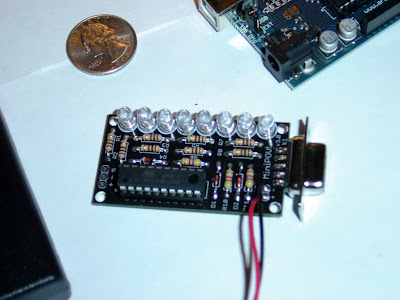
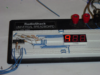
I found an old keyboard with a 7-segment display. Lots of other interesting things in the device, but sadly most of it was a huge 100-pin surface-mount chip. I did get this 7-segment going though, driven by a 74hc4511 (also from the keyboard) and the Arduino.

The 74hc4511 takes BCD digits and drives the 7-segment. It also handles source current for the LEDs, so I don't have to worry about the ATmega in the Arduino and/or a transistor array. Right now it's only driving a single digit, but with a small modification it can drive all three.

If I wire all the common segments together (all the A segments, B segments, etc) and add a sink transistor controlled by an output pin on the Arduino, all three digits can be driven. If you alternate between the three fast enough, there's no flicker and you can drive all three. Of course that takes a lot of work.

Another way would be to use 3 shift registers. Shift in 3 bytes and just forget about it. They won't do BCD conversion, but that's just a nifty plus anyway. It's easy enough to do in software. You can also drive as many digits as you want that way.

There are two ways of wiring it up. You can either wire the shift out pin of one register to the shift in pin of another register. This will allow you to drive all the digits with just one pin, but means you have to shift out all the digits every time you want to update the display. Or you can wire each shift in pin to an IO pin. This takes more IO pins, but could be handy if there are multiple, unrelated displays.

Wednesday, September 05, 2007

The MiniPOV3 kit


I got a MiniPOV3 kit from Adafruit.com with my Arduino, and I decided to solder it up tonight. Soldering was a bit tricky since I only have a cheap radio shack soldering iron and nothing to properly hold the PCB in place, but I got it all right. As you can see from the pictures, I didn't make a mess of the soldering.

The MiniPOV3 is a really cool kit. You can reprogram it yourself or modify it to do anything else you want. It includes a place on the PCB for a sensor. Maybe I'll see if I can hook up a tilt switch or mercury switch or something. An accelerometer would be awesome.

More pics

Tuesday, September 04, 2007

Driving a stepper motor


I found a stepper motor in a scanner and decided to hook it up. They're dead easy to drive from the parallel port. All you have to do for normal stepping is pulse the pins in order. Each pin goes a transistor that hooks the motor coils to a 9v power supply. And that's it, very easy.

I tried to get the pulses as small as possible, but under 10ms per pulse it gets pretty flaky. This probably has more to do with the fact that I'm severely underpowering the coils. They should be getting more like 24v, not 9v. It works, but it has almost no torque.

I also did "high torque stepping" by powering not only the coil I want to move the motor to, but also the coil after that. I think I'm getting slightly more torque, but still not much. I did microstepping too, which powers the coil you want to move to, plus the coil after the next. This kind of gets the rotor stuck between two steps. It allows for finer control (moving in half steps) and smoother motion (stepper motors are "jerky").

I just got my Arduino and replicated the same stuff on it. I'll post picture of that later after more experimentation.

Power supply


I don't have a DC power supply to use, so I made one out of a 9.6v NiCad battery pack from a remote control car.  I can supply up to about 9v and is of course rechargable and I don't have to worry too much about short circuits.

It uses an LM317 adjustable voltage regulator and a potentiometer to select the voltage.  There are two led indicators and two switches.  The first switch turns the input on.  At this point, you can change the voltage with the potentiometer (monitoring with a mulitmeter).  The second switch turns the output on so you can adjust the voltage without powering anything else.  The second indicator light is for the output circuit.

I wrapped up the battery pack's cord nicely, put the power supply circuit on a small breadboard and it's all held together with wire ties.  It's pretty ghetto, but hey, it cost about $1 (the price of the LM317 at radio shack).